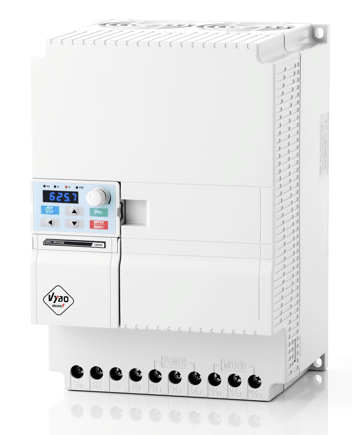
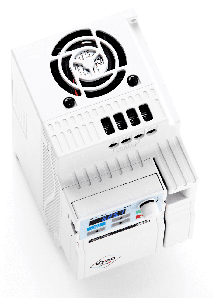
Variable frequency drives V800
Variable frequency drives V800
The V800 series variable frequency drives are compatible with vector control. Manufactured to the highest possible quality with the most demanding features, they are able to control drives on a professional level. They have special software and many features that enable them to operate even in the harshest conditions of heavy industry. The V800 is fully pre-programmed and ready to use. All you have to do is plug them into the mains. They can be operated directly from the panel or externally in analog and digital. They are suitable for the most demanding applications with very high overload capacity.
Variable frequency drive V800 – Functions
– Power supply to the frequency converter with 1 x 230 V AC or 3 x 400 V AC
– Frequency converter control mode is SFVC open circuit vector or V/F control
– Converter output frequency 0.01 to 3200 Hz
– The V800 operates with a carrier frequency of 1 to 16 kHz
– The V800 has a standard built-in brake unit, PID, PLC
– Built-in EMC filter
– Standard AVR, JOG, Timers, Protections
– EMS immediate stop safety function
– Connection function of PTC protection or electric motor thermocontact
– Removable panel with external installation up to 50 m (by cable)
– The V800 has 6 digital inputs, including 1 high-speed 100 kHz pulse; 2 analog inputs 0-10 V and 4-20 mA.
– The outputs are 1 digital, 1 analog and 1 relay
– RS 485 MODBUS physical interface built in as standard
– MODBUS RTU communication interface
– Standards EN/IEC 61800-3: 2017; C1 which is suitable for 1. environment; EN/IEC 61800-3: 2016; C2, which is suitable for 1. environment
The VECTOR V800 is a new type of frequency converter suitable for industrial processes. They can operate at an output frequency of up to 3200 Hz. The V800 series has non-feedback vector control and V/F control. The basic equipment includes a built-in brake unit, EMC filter, PID, PLC, AVR, JOG, Timing control, EMS safety stop system, input for connection of PTC protection or electric motor thermal contact, MODBUS communication, etc. The V800 features 6 digital inputs, including 1 high-speed 100 kHz pulse; 2 analog inputs 0-10 V and 4-20 mA. The outputs are 1 digital, 1 analog and 1 relay. The converter panel is removable with the possibility of external installation up to approx. 50 m by cable. The V800 frequency converter is factory-set and in the basic application it is sufficient to connect the wiring correctly and to enter the START command.
Frequency inverter V800 – Industrial use:
– pumps
– ventilation
– textiles
– grocery store
– electric gearboxes
– ceramics
– grinders
– centrifugal machines
– cutters
– diving machines
– cutting machines
Variable frequency drives
| Item | VECTOR V800 |
| Control mode | V/F (Voltage/Frequency) control; Senseless flux vector control (VC) |
| Maximum frequency | Vector control: 0-300Hz; V/F control: 0-3200Hz |
| Carrier frequency | 1,0-16,0 kHz; The carrier frequency is automatically adjusted based on the load features. |
| Input frequency solution | Digital setting: 0,01 Hz; Analog setting: 0,025% of maximum frequency |
| Startup torque | G type: 0,5Hz/150% (VC), P type: 0,5 Hz/100% (VC) |
| Speed range | 1:100 (SFVC) |
| Stability accuracy | ± 0,5% (SFVC) |
| Torque control accuracy | ± 5% (SFVC) |
| Overload capacity | G type: 60s for 150% of the rated current, 3s for 180% of the rated current |
| Torque boost | Auto boost; Customized boost 0,1%-30,0% |
| EMC filter | Integrated with C1 marking. Without integration C2 marking. |
| V/F curve | Line V/F curve; Multi-point V/F curve; N-power V/F curve (1,2 power, 1,4 power, 1,6 power, 1,8 power, square) |
| V/F separation | Two types: complete separation; half separation |
| Ramp mode | Straight-line ramp; S-curve ramp; Four groups of acceleration/deceleration time with the range of 0,0-6500,0s |
| DC braking | DC braking frequency: 0,00 Hz to maximum frequency; Braking time: 0,0-100,0s; Braking action current value: 0,0%-100,0% |
| JOG control | JOG frequency range: 0,00-50,00 Hz; JOG acceleration/deceleration time: 0,0-6500,0s |
| Onboard multiple preset speeds | It implements up to 16 speeds via the simple PLS function of combination of terminal states. |
| Onboard PID | It realizes process-controlled closed loop control system easily. |
| Auto voltage regulation (AVR) | It can keep constant output voltage automatically when the main voltage changes. |
| Overvoltage / Overcurrent stall control | The current and voltage are limited automatically during the running process so as to avoid frequent tripping due to overvoltage/over current. |
| Torque limit and control | It can limit the torque automatically and prevent frequent over current tripping during the running process. |
| EMS STOP safety function | “Emergency STOP” system: In emergencies, the inverter stops immediately after EMS STOP is activated. |
| Rapid current limit | It helps to avoid frequent over current faults of the AC drive. |
| High performance | Control of asynchronous motor is implemented through the high-performance current vector control technology |
| Timing control | Time range: 0,0-6500,0 minutes |
| Communication methods | RS485 (MODBUS-RTU) |
| Running command source | Operation panel/Control terminals/Serial communication port. You can perform switchover between these sources in various ways. |
| Frequency source | Digital setting, analog voltage setting, analog current setting, pulse setting and serial communication port setting. |
| Auxiliary frequency source | There are ten auxiliary frequency sources. It can implement fine tuning of auxiliary frequency and frequency synthesis. |
| Input terminal | 6 digital input terminals, one of which supports up to 100 kHz high-speed pulse input. 2 analog input terminals, one of which only supports 0-10 V voltage input and the other supports 0-10 V voltage input or 4-20 mA current input. |
| Output terminal | 1 digital output terminal; 1 relay output terminal; 1 analog output terminal that supports 0-20 mA current output or 0-10 V voltage output. |
| LED display | It displays the parameters. |
| Key locking and function selection | It can lock the keys partially or completely and define the function range of some keys so as to prevent mis-function. |
| Protection mode | Motor short-circuit detection at power-on, input/output phase loss protection, over current protection, overvoltage protection, under voltage protection, overheat protection and overload protection. |
| EMC (Compatibility) | IEC 61000-4-6; IEC 61000-4-4;IEC 61000-4-11; IEC 61000-4-5 |
| Standards | EN/IEC 61800-3: 2016; C1 which is suitable for 1. environment; EN/IEC 61800-3: 2016; C2 which is suitable for 1. environment; |
| Installation in the environment | Inside, avoid direct sunlight, salt, dust, corrosive or flammable gas, smoke, steam. Resistance to chemical pollution class 3C3 EN/IEC 60721-3-3. Dust resistance 3S3 EN/IEC 60721-3-3. |
| Height above sea level | Below 1000 meters above sea level. (reduce the load level when used above 1000 meters above sea level) |
| Ambient temperature | -10°C ~ 40°C (reduce the power level if the ambient temperature is between 40°C and 50°C) |
| Humidity | Less than 95% relative humidity, without condensation IEC 60068-2-3 |
| Vibration | Less than 5.9 m/s2 (0.6 g) IEC 60068-2-6 |
| Storage temperature | -20°C to +60°C |
Online contact
00421 948 834 888
(international sales manager)
Email: fv@vyboelectric.eu