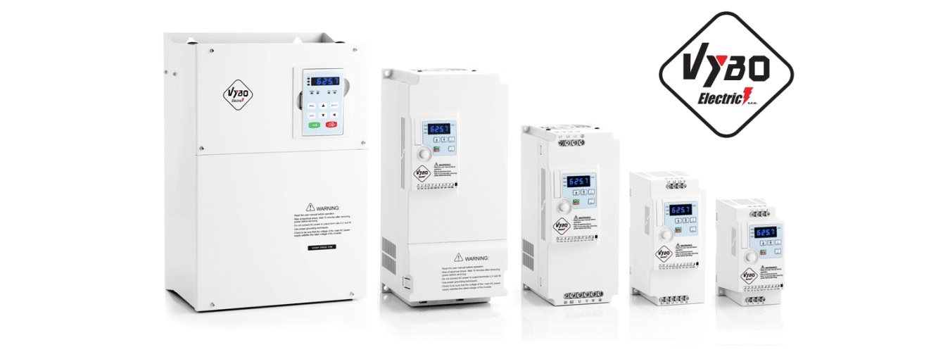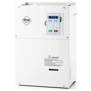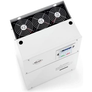
Variable frequency drives 500kW 400V V810 VYBO Electric
500kW V810 VFD’s on stock. The V810 series frequency converters are designed for the most demanding and most complicated professional applications. These are vector frequency converters with a wide range of applications. They handle an overload of up to 180% for 3 seconds and an overload of 150% for 60 seconds. It is the highest class of frequency converters, which are mass-produced up to 1000kW. They are destined to handle huge loads. The large performance range with different frequency converter configurations and many additional options allows the use of one platform for a number of requirements. Our inverters are used all over the world.
500kW VFD V810 can be used in many applications
Variable frequency drive V810 500kW is very versatile. It can be used in many applications. The frequency inverters of the V810 series belong to the category of inverters for heavier operation because they can handle even more demanding industrial applications. In practice, they can have a really rich use across different industries. Their use ranges from simpler applications in textile production to demanding drives in the energy, mining or automotive industries.
Advantages of 500kW V810 frequency converters
The main features of 500kW V810 frequency converters include: quality, efficiency and reliability. The devices are manufactured with the greatest possible precision from the highest quality materials. Their wide performance range and advanced technology guarantee efficient regulation of electric motors in the entire spectrum of industry. Thanks to many years of experience and development of V810 inverters, we produce the highest and most reliable product on the market in the given category. Frequency converters have, among other things, many advantageous features and various standard and non-standard functions.
A brief overview of the functions of the V810 series inverter
- Power supply of the inverter to three-phase voltage 3 x 400 V
- Basic functions: timers, protections, AVR, JOG …
- Built-in EMS STOP (for immediate stop)
- Function for connecting PTC protection or thermal contact of the electric motor
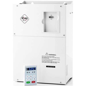
- Detachable panel and the possibility of external installation with a cable up to 50 m
- Communication interface via MODBUS RTU; PROFIBUS-DP
- Physical interface via RS 485 MODBUS
- The output frequency range is 0.01 to 3200 Hz
- The carrier frequency range is 1 to 16 kHz
- Frequency converter control mode is CLVC (closed circuit vector), SVC (open circuit vector) or V/F (scalar control)
- Model V810 is equipped with a brake unit up to 18.5 kW, PID, PLC
- 8 digital inputs available, including 1 high-speed pulse input (100 kHz); 2 analog inputs -10/+10 V; 0-10 V and 4-20 mA (or 0 to 20 mA).
- 5 outputs available: 1 digital – high speed, 2 analog and 2 relays
- Built-in port for connecting PG cards (encoder, resolver, etc.)
- Standards EN/IEC 61800-3: 2017; C1, which is suitable for the 1st environment; EN/IEC 61800-3: 2017; C2, which is suitable for the 1st environment;
- The model is manufactured in power ranges up to 1 MW
V810 frequency converters – price list
Although we do not have a price list for V810 series frequency converters online, you can request a price from us via the form, where you just need to state your name, e-mail and write in the message what device you are interested in. Our team of specialists will try to send you all the necessary information to your e-mail as soon as possible. If you prefer a phone call, feel free to call us on our customer line and we’ll be happy to help you buy a new frequency converter. All contact info is in the header of our site.
| Item | VECTOR V810 | |
|---|---|---|
| Power | Power | Input voltage range: 1 x 230 V AC ± 15% 3 x 400 V AC ± 15% 3 x 690 V AC ± 15% Power frequency range: 47 to 63 Hz |
| Standard Features | Control Mode | V / F scalar control SVC vector with open circuit CLVC Vector Control |
| Maximum frequency | SVC, CLVC vector control: 0 – 300 Hz V / F scalar control: 0 – 3200 Hz |
|
| Carrier Frequency | 1-16 kHz The carrier frequency is automatically set based on the load characteristic. |
|
| Input frequency resolution | Digital setting 0.01 Hz Analog setting: maximum frequency x 0.025% |
|
| Initial torque | G type: 0.5 Hz / 150% (SVFC) G type: 0.5 Hz / 180% (CLVC) P type: 0.5 Hz / 100% (V / F) |
|
| Speed range | 1: 100 (SVC) 1: 1000 (CLVC) |
|
| Speed stability | ± 0.5% (SVC) ± 0.02% (CLVC) |
|
| Torque control accuracy | ± 5% (CLVC) | |
| Overloadability | G type: 60s for 150% of rated current, 3s for 180% of rated current P type: 60s for 120% of rated current, 3s for 150% of rated current. |
|
| Increase torque | Auto-boost or user manual increment 0.1% to 30.0% | |
| V / F curve | Linear V / F curve Multipoint V / F curve N-voltage V / F curve (multiple of 1.2-voltage, 1.4-voltage, 1.6-voltage, 1.8-voltage, adjusted) |
|
| V / F separation | Two types: full separation; half separation | |
| Ramp modes | Linear ramp S-curve ramp Four groups of acceleration / deceleration times with a range of 0.0-6500.0 s |
|
| Input and Output | Input terminals | 8 digital inputs, binary ON / OFF inputs, 1 terminal X5 can support high speed pulse input. All terminals have optional PNP or NPN 2 analog inputs, one of which FIV supports -10 V / +10 V; or a 0-10 V input and the second FIC supports a 0-10V or 0-20mA (4-20 mA) input. |
| Output Terminal Blocks | 1 Programmable open collector output: provides 1 output terminal (open collector output or high speed pulse output) 2 relay outputs, 2 analog outputs: FOV and FOC with optional 0 – 20 mA (4 – 20 mA) or 0 – 10 V output |
|
| PG | PG cards | The drive is equipped with a port for PG cards (for encoder), or PG cards for use with a resolver, etc. |
| Standard Features | DC braking | Braking frequency: 0.0 Hz to maximum frequency Braking time: 0.0-36.0 s Braking current value: 0.0% -100.0% |
| Brake unit | Models up to 18.5 kW have a built-in brake unit as standard. | |
| Control in JOG mode (stepping) | JOG frequency range: 0.00-50.00 Hz JOG acceleration / deceleration time: 0.0-6500.0 s |
|
| Implem. more preset speeds | Implemented up to 16 speeds using a simple PLC function or a combination of X end states. | |
| PTC / Termokontakt | Input for PTC motor or thermal contact protection. | |
| Built-in PID regulator | Facilitates a process-controlled closed-loop control system. | |
| Automatic AVR voltage regulation | It can automatically maintain a constant output voltage when the supply voltage changes. | |
| Overvoltage and overcurrent control | Current and voltage are automatically limited during operation to prevent frequent tripping due to overvoltage and overcurrent. | |
| Torque and steering limitation | It can automatically limit torque and prevent frequent overcurrent changes during operation. | |
| EMS STOP security feature | Emergency stop system: in an emergency, the drive stops immediately after activating EMS STOP. | |
| Fast current limit | Helps prevent common errors due to AC motor overcurrent | |
| High performance | AC motor control is performed by high-performance vector current control technology. | |
| Time Management | Time range: 0.0-6500.0 minutes | |
| Communication | MODBUS RTU, PROFIBUS-DP | |
| Boot Command Channel | Depending on the panel, control terminals, the serial communication port can be switched in many ways | |
| Frequency source | 10 types of frequencies, given by digital analog voltage, analog current, pulse, serial port, X8, PID, can be switched in many ways | |
| Auxiliary frequency source | 10 kinds of frequencies, micro adjustment can be easily implemented, frequency synthesizer | |
| LED display | Displays parameters | |
| Lock keys and select features | Can block buttons partially or completely and define the range of functions of some buttons to prevent malfunctions. | |
| Protection mode | Motor short-circuit detection, output phase loss protection, overcurrent protection, overvoltage protection, live protection, overheat protection and overload protection. | |
| EMC (compatibility) | IEC 61000-4-6; IEC 61000-4-4, IEC 61000-4-11; IEC 61000-4-5 | |
| Standards | EN / IEC 61800-3: 2017; C1, which is suitable for the 1st environment; EN / IEC 61800-3: 2017; C2, which is suitable for the 1st environment; |
|
| Installing in an environment | Install indoors, avoid direct sunlight, salt, dust, corrosive or flammable gas, smoke, steam. Resistance to chemical contaminants class 3C3 EN / IEC 60721-3-3 .Dust pollution resistance 3S3EN / IEC 60721-3-3. |
|
| Nadm. height. | Under 1000 meters above sea level. (reduce the power level when used above 1000 meters above sea level.) | |
| Ambient temperature | – 10 ° C ~ 40 ° C (reduce power level if ambient temperature is between 40 ° C to 50 ° C) | |
| Humidity | Less than 95% relative humidity, no condensation IEC 60068-2-3 | |
| Vibration | Less than 5.9 m / s2 (0.6 g) IEC 60068-2-6 | |
| Storage temperature | – 20 ° C ~ 60 ° C | |
Availability: In stock
Online contact
00421 907 937 187
mv@vyboelectric.eu

Model
V810-4T5000G
Power
500 kW
Nominal current
860 A
ISO certificates


24h/7/365 emergency service
Warehouse and factory in the EU (Slovakia)
VFD´s directly from stock
Custom design and individual adaptations
Express fast delivery
Optional accessories
